A click worth getting back
Most of us barely notice moving a cursor. For someone who has lost the use of their hands, making it move can restore a measure of independence. In January 2026, Neuralink reported 21 participants enrolled worldwide and described people using its implant to control computers, make art and operate an assistive robotic arm.17
The engineering question begins just beneath that ordinary-looking click. A thread has to reach brain tissue. An electrode has to collect a useful signal. Electronics must remain protected, decide what to transmit and hand enough information to software that can turn an intention into the right command. Each transition is a place to lose the connection.124518
Neuralink’s patents let us examine those transitions closely. They also contain a much stranger proposal: placing a layer of living neurons above the cortex and using that graft as part of the interface. We will get there by following the hardware first. The patents reveal designs and claimed inventions; a match to a problem in the clinical system does not establish that a particular patented design is inside a participant’s implant.819
What the trial implant actually does
Neuralink’s March 2024 description of N1 specifies 1,024 electrodes distributed across 64 flexible threads. The threads feed electronics inside an implanted enclosure; processed neural data travel wirelessly to an application on an external device. The application decodes those data into computer control. This documented architecture is our starting point; later hardware revisions may differ.18
The UK GB-PRIME1 study summary describes a wireless, rechargeable N1 implant, an R1 robot that helps place the threads, and recording from the motor cortex to control devices such as a cursor or virtual keyboard. Its stated purpose is to evaluate initial safety and device functionality in an early feasibility study. That is the clinical context for this story.19
Now follow one of those threads. Before there can be a command on a screen, there has to be an electrical contact that can survive being part of something soft.
The contact lives at the edge
The useful detail in US12539083B2 is small enough to disappear in a product rendering. Figure 1C cuts across the electrode assembly: insulating material shelters the conductors, while a contact is exposed at the side. In the lower cross-section, the exposed contact sits on a dielectric base. The drawing makes the tradeoff visible—protect the wiring while leaving a controlled place to pick up activity from nearby tissue.112
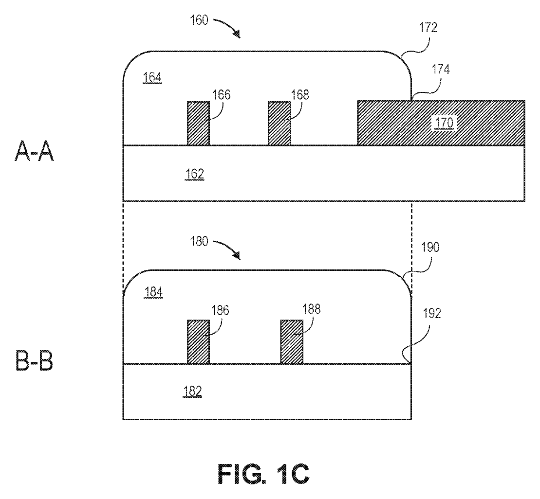
Issued claim 1 is quite specific about that arrangement. The contacts are confined to a side edge along the flexible dielectric. The exposed part lies entirely below its top edge, extends beyond its side edge, and has dielectric covering its bottom. The September 2025 amendment explicitly added that last requirement; the February 2026 grant retains it.19
This is a case where the abstract can lead a reader astray: it describes an embodiment with a contact protruding beyond the top edge. The issued claim instead requires the exposed portion below it. The contact’s vertical position is part of the claimed combination, so the issued claim is the useful guide to this drawing.1
A soft thread needs a temporary backbone
A flexible lead presents an awkward handling problem: the quality that makes it compliant also makes it difficult to push into tissue. US12042174B2 describes an assembly that lets a needle carry the lead, with a cannula holding and guiding the needle. The drawings show the lead approaching a small gate near the needle’s exit.213
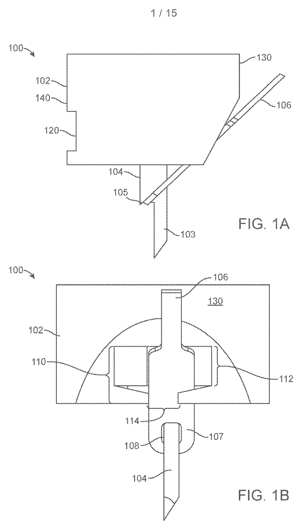
Claim 1 spells out the handoff. The lead has an opening surrounded by an expanded end region. The needle passes through that opening and catches it on a ledge. As the needle extends, the lead comes through a slot in the exit gate and leaves the gate’s aperture. Dependent claim 2 adds a temporary attachment surface from which the needle peels the lead. This is an invention about reliably picking up, transporting and releasing something too delicate to handle as a rigid probe.2
Finding that tiny opening is a second problem. US11291508B2 claims illuminating a polymer part of the electrode with near-ultraviolet light, using two cameras to triangulate the fluorescent target, and imaging the insertion needle under visible light. The robot then uses those positions to engage the polymer loop and implant the electrode. The claim specifies 300–425 nanometers for that first illumination step.3
Together, the two records expose the choreography behind insertion: see the target, catch it, move it and let it go. They are useful design evidence for understanding the surgical challenge, not a verified parts list for the current R1 robot.
The enclosure has to close around the wires
The implant’s radio can send data across intact skin. Inside the body, however, the electrode wiring still has to pass into the protected electronics. US12653064B2 puts that less glamorous boundary at the center of the design. Its exploded drawing shows a ribbon of conductors passing between two enclosure portions.18414
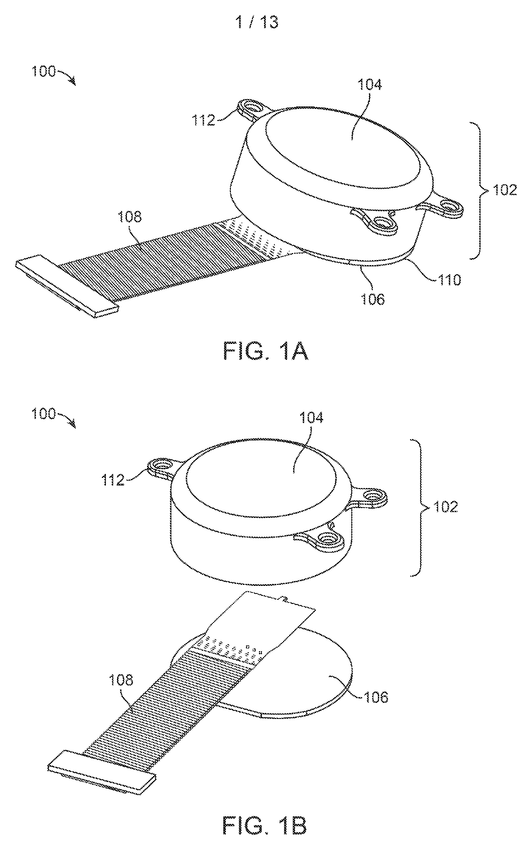
Issued claim 1 requires both portions to use PCTFE, a fluoropolymer. Parallel insulated wires, separated from their neighbors by less than 150 micrometers, run between them. A thermal weld must join the two portions and conform around the insulation of every wire to seal the enclosure. Dependent claim 4 specifies at least 500 wires; the broad claim does not require that count.4
The seal therefore has two jobs at once: join the housing and close around an array of closely spaced feedthroughs. That helps explain why increasing channel count is also a packaging problem. More signal paths have to cross the same protected boundary. The patent supplies a manufacturing approach; it does not, by itself, establish a lifetime of leak-free operation in people.4
Keeping a signal is different from getting one
Contact geometry and sealed packaging still leave a moving biological interface. In its January 2026 update, Neuralink acknowledged thread retraction in its first participant and described changes intended to improve signal retention. It also outlined plans to increase electrode count from roughly 1,000 to 3,000, investigate mechanical retention features and explore insertion through the dura, the membrane around the brain. Those were stated development directions, not confirmation that a 3,000-electrode version had entered use.17
That distinction matters when reading a growing patent portfolio. A new grant can protect work filed years earlier. A company roadmap can point toward a revision that the public record does not yet document. The connection we want to understand is the one that continues producing useful information after the insertion has ended.
The implant decides what is worth sending
The signal at an electrode is a changing voltage. In Fig.1 of US12688941B2, some excursions cross a threshold while others remain in the background. The drawing introduces a selection problem: which pieces of this stream deserve to leave the implant? The issued claim goes beyond a simple threshold crossing.515
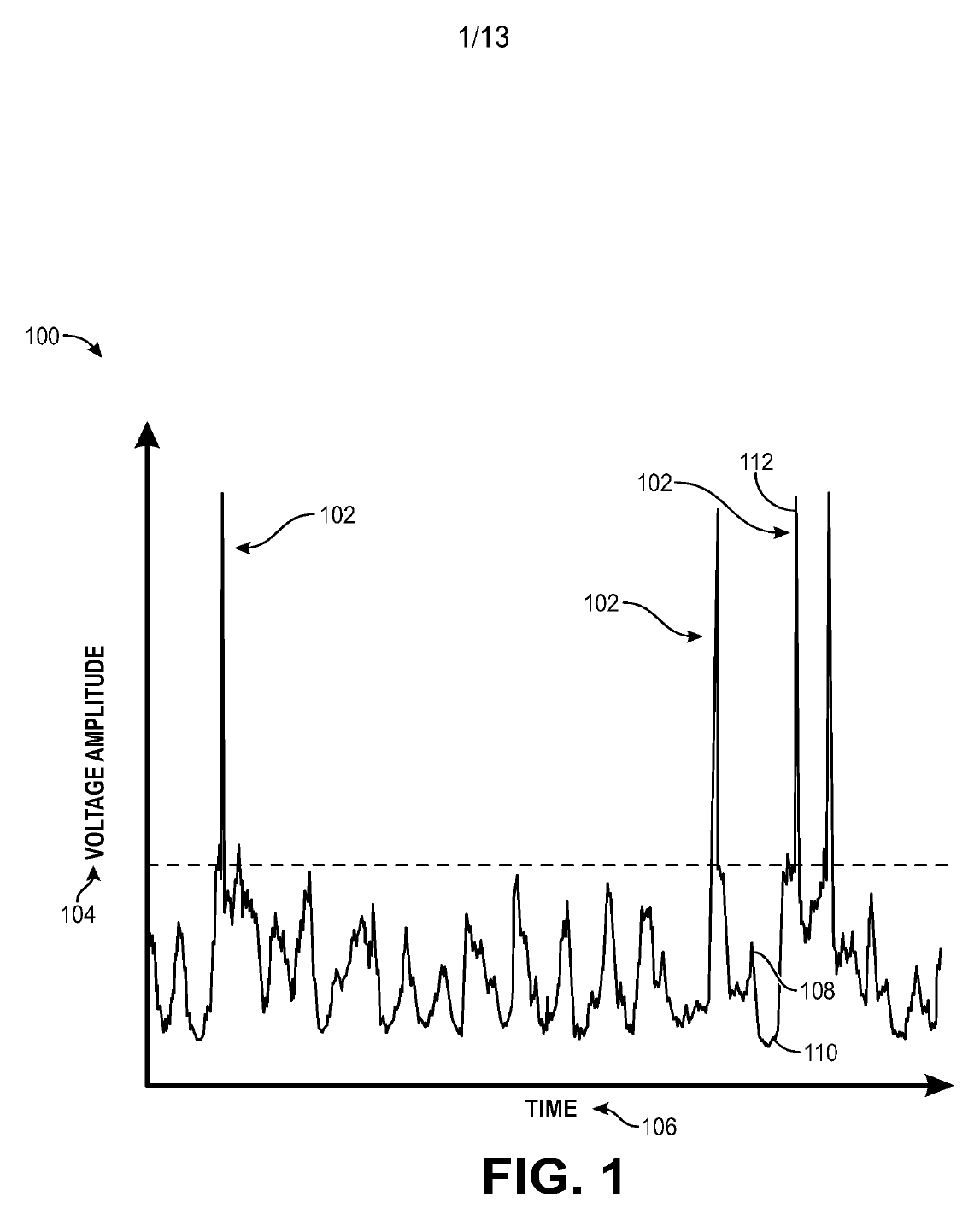
Claim 1 filters a recorded signal, fits it to a model and finds a local minimum plus the maxima before and after it. Circuitry compares selected amplitude and timing relationships with thresholds, using fixed-point arithmetic with fewer bits than floating-point representations. When it classifies a neural spike, it sends a smaller indication of the event to a remote receiver. Otherwise, it discards the received signal instead of transmitting it.5
This is an economical way to describe the engineering objective: preserve useful events without carrying every sample forward. It addresses processing and transmission work inside the implant. The claim does not make those events equivalent to thoughts, words or intentions; turning neural information into a useful command is a further job for decoding software.518
When the cursor gets it wrong
Imagine trying to move away from a button while helpful software keeps snapping the cursor back onto it. Neuralink’s US11630516B1 uses this kind of frustrating interaction to explain an interface-aware controller. The specification also discusses detecting repeated backspaces and adapting the interpretation of subsequent input.6
Issued claim 1 makes the recovery sequence unusually concrete. A first model interprets neural signals as a command. Further neural signals are used to detect frustration. The system then sends a cancellation of that first command, routes a second set of signals to a second model and sends the new interpretation. The claimed chain is error detection, cancellation and a change of decoder.6
That is a useful way to think about a brain-controlled interface: a wrong click needs a way back. But a patent that specifies detecting frustration is not validation of a dependable emotion detector in a clinical product. It records a proposed control strategy and the combination claimed, including the neural-signal basis of that detection.6
Pairing a device that has no screen
There is one more ordinary computer problem made unusual by an implant: establishing which external device it should trust. US12547711B2 describes a pairing arrangement with two external devices. One is trying to make the wireless connection; a different device supplies a varying magnetic field that carries a pairing code.7
In claim 1, the implant detects and analyzes that field, uses the code in a key exchange, compares the exchanged values and confirms or rejects the wireless connection. A dependent implementation makes the separate device a charger. The physical channel gives the pairing process another way to convey a code to an implant that cannot display one on a screen.7
The patent also has a separate independent claim using neural signals for pairing. That gives it two distinct routes for establishing the connection: a physical magnetic channel and an interpreted neural signal. Authentication, like insertion and sealing, has to be designed around the body.7
The frontier: grow part of the connection
The cell-based application, US20230077899A1, asks whether living cells could become part of the bridge. It describes grafting neurons above the cortex’s outer layer to form what it calls Layer Zero, or L0. Processes growing from the graft extend into the underlying brain. The drawings explore reading that layer optically or placing an electrode array over it.816
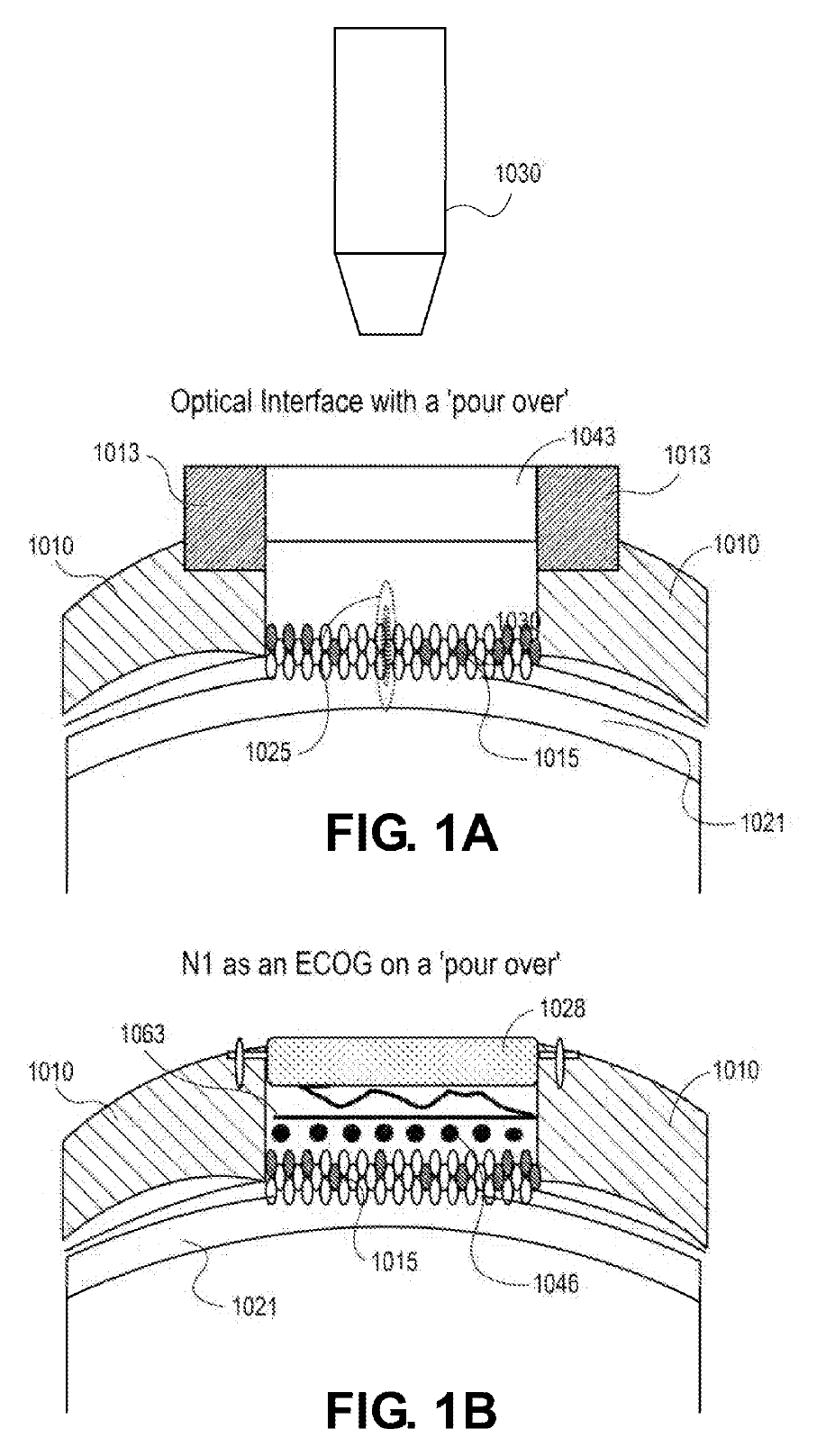
There is experimental material behind the proposal. The specification reports mouse graft observations and a task in which mice modulated activity in the grafted layer to obtain rewards, with performance above chance by the third day. It also reports control experiments that changed the relationship between neural activity, auditory feedback and reward. These are findings reported in the patent’s mouse work; they do not demonstrate a durable cell-based implant in a person.8
The attraction is easy to see. Instead of asking only how to move an electrode toward a neuron, the proposal asks whether a deliberately placed living layer can connect into existing circuitry while remaining accessible to a recording or stimulation device. The hard questions shift with it: what connections form, how stable they remain and how reliably activity in that layer can support a useful task. Those are the questions a future human system would have to answer.
The file history gives that frontier a shape
The application moved beyond its original published claims during examination. In June 2026, amended claim 1 specified a graft of exogenous neuronal cells together with processing circuitry, a camera to read the graft and a light source to send information to it. It also requires the cells to be configured to penetrate the brain from the outermost cortical layer through growing processes.10
The examiner allowed that claim and others on August 20, 2026. The additional independent claims matter: claims 36 and 37 retain approaches with cells tethered to electrodes, while claims 38 and 39 separately address optical transmission and optical reading. The allowed application is therefore broader in its menu of approaches than the camera-plus-light combination in claim 1 alone.1011
As of this review, the retrieved record shows an allowed application, not an issued patent for this cell-based case. Allowance tells us what passed this stage of patent examination. It does not tell us whether a cell graft is ready for human use, or that it is a scheduled successor to N1.118
The next breakthrough still has to make a good connection
A cursor moving across a screen hides a remarkable chain of dependencies. The electrode needs an exposed contact and protected wiring. The insertion tool has to carry something soft. The package must close around its conductors. Signal processing has to preserve useful information, and the interface has to recover when it interprets the user incorrectly.12456
The living-interface proposal is compelling because it revisits the first link in that chain. Even there, the record returns to practical hardware: cameras, light sources, electrodes and processing circuits. Biological integration would change the connection, while leaving the demand for reliable communication intact.10
For the person at the computer, the test remains wonderfully ordinary: can I do the thing I meant to do, and can I keep doing it? That is a strong lens through which to read the next Neuralink patent.
Evidence notes, claim details and open questions
What this review covers
Research cutoff: September 14, 2026. This article examines seven issued US patents and one published US application, with selected claim pages, descriptions, original filed drawings and the two claim-amendment / allowance issues discussed above. Every publication number in the article opens a self-hosted original PDF. The inline figures come from the actual file histories and retain their original labels.1234567891011
Company reports and clinical-study descriptions establish the documented implant context. They do not establish implementation of every patented feature. January 2026 enrollment and development plans are deliberately dated. The patent descriptions of mouse grafts and interface control are not treated as human clinical results.17181986
The selected records expose eight US nonprovisional applications and four provisional links. All 890 documents in the platform’s index for those twelve files were confirmed downloaded on September 14. OCR remains in progress. This article reviews the selected material identified above; collecting a file does not mean every page has been substantively reviewed, and these records do not establish a complete worldwide Neuralink portfolio.
The family section now includes four original patent-platform SVGs: electrode contact, robot vision, spike detection and the cell-based interface. The platform has no family mapping for the cannula, enclosure, interface-controller or pairing applications. Its family records list PCT links that its SVG renderer currently omits; those missing PCT identifiers are called out below the unchanged diagrams. Family coverage remains incomplete. The platform’s recorded assignment chains identify transfers to Neuralink Corp., including the cell-based case; a record of an employment agreement is not counted as a transfer of title.